
toshiba_air_cond
AB protocol decoder for toshiba air conditioners
Stars: 64
The toshiba_air_cond project implements functions to decode Toshiba AB protocol from indoor units to wired controllers and provides a hardware design for communication. It is developed for ESP8266 using PlatformIO and Wemos D1 mini board. The project offers features such as WebServer, WebSockets communication, Home Assistant integration, OTA updates, file uploading, and WiFiManager. It has been tested with specific Toshiba units and provides a web interface for controlling functions like power ON/OFF, setting target temperature, changing modes, adjusting fan speed, setting timers, and displaying current temperature and system information.
README:
This project implements functions to decode Toshiba AB protocol from indoor units to wired controllers and provides a hardware design for communication.
Gerbers are available but remember if you improve the design please share it, that's how open source works, if you do not want to share, this project is not for you.
I strongly recommend to use makusets' board instead of my custom hardware. My hardware is designed assuming a voltage level of the AB line around 15.6V when "1" and 14V when "0". Different voltage values will not work for writing while reading will work.
In particular, this project has been tested with remote control unit RBC-AMT32E and central unit RAV-SM406BTP-E (http://www.toshiba-aircon.co.uk/assets/uploads/product_assets/20131115_IM_1115460101_Standard_Duct_RAV-SM_6BTP-E_EN.pdf)
You can find the service manual from central unit and wired controller here: http://www.toshibaclim.com/Portals/0/Documentation/Manuels%20produits/SM_Gainable_Std-Compact--DI_406566806110614061606_GB.pdf, https://rednux.com/mediafiles/Hersteller/toshiba/Toshiba-Bedienungsanleitung-RBC-AMT32E-Englisch.pdf
Code is developed in PlatformIO for ESP8266 and in particular for Wemos D1 mini board. It is basically a WebServer that serves a webpage and communicates with the client by means of WebSockets. It also offers Home Assistant integration and has nice features usch as OTA updates, file uploading, WifiManager and others.
This project uses libraries and code from different authors, they are installed automatically from platformio.ini file
- esp8266
- espsoftwareserial by Peter Lerup
- WiFiManager by tzapu
- WebSockets by Links2004
- ArduinoJson by Benoit Blanchon
- Adafruit libraries Adafruit SSD1306, Adafruit GFX Library, adafruit/Adafruit AHTX0 and adafruit/Adafruit BMP280
- LittleFS
- PubSubClient
- NTPClient
First things first. Compile it with VSCode and upload it to the board with PlatformIO.
Minimal hardware is ESP8266 and the pcb for adapting signal from serial to AB line.
- ESP8266 (Wemos D1 Mini R2)
- Toshiba AC serial interface (SoftwareSerial D7=RX, D8=TX)
- Optional I2C sensors (shared bus D1=SCL, D2=SDA):
- AHT20 (temperature + humidity) [enabled with
#define USE_AHT20] - BMP280 (temperature + pressure) [enabled with
#define USE_BMP280] - BME280 (temperature + humidity + pressure) [enabled with
#define USE_BME280]
- AHT20 (temperature + humidity) [enabled with
- Optional OLED 128x64 SSD1306 (I2C D1=SCL, D2=SDA) [
#define USE_SCREEN] - Reset / Config button on D4 (WiFiManager AP)
To sum up, the following defines are available and features are disabled by commenting its #define in config.h
-
USE_OTAOTA updates -
USE_SCREENOLED status display -
USE_MQTTMQTT + Home Assistant integration -
USE_AHT20AHT20 sensor support -
USE_BMP280BMP280 sensor support
Once you have the code uploaded it is time to configure your WiFi. This project makes use of the great WiFiManager library so there is no need to hardcode your WiFi settings.
- Plug you esp board. It will start blinking.
- Connect to airAP wifi network from your cellphone or PC.
- Open a browser and the WifiManager will appear.
- Select your WiFi network and the password.
- If everything is correct, airAP shuts down and board connects to your WiFi.
- Connect to your normal WiFi from computer/cellphone.
Now the esp8266 is connected to your network and can be reached as http://air.local
Connect to http://air.local/filemanager, type and upload it.
This will store index.html file and http://air.local should show the main page. You can use this endpoint to modify the webpage or add more functionality. If you do it please share.
Similarly to upload page you can use http://air.local/filemanager to delete a file.
OTA updates are available, so you do not need to unplug the esp everytime you want to flash it. In the Arduino IDE just set Tools->Port->air at xxx. If you are using PlatformIO it is done in platform.io Default OTA password is esp8266
; OTA upload configuration
upload_protocol = espota
upload_port = air.local        ; Replace with your device's actual IP from OTAName in config.cpp
upload_flags = --auth=esp8266  ; Replace with your OTA password from OTAPassword varialble in config.cpp
If you just want to upload individual files you can use http://air.local/edit.html
This section describes the features available through the embedded web interface served by the ESP8266 air conditioning controller.
- URL via mDNS:
http://air.local(SeemdnsNameinconfig.h) - HTTP Port: 80
- WebSocket Port: 81
)
-
Control Functions
- Power ON / OFF
- Set target temperature (bounded 16–30 °C; internally enforced 18–30 in MQTT handler)
- Change mode:
cool,heat,dry,fan_only,auto,off - Change fan speed:
auto,low,medium,high - Save mode
-
Timer
- ON/OFF Timer. Software based relying only in esp8266
-
Chart
- Shows current temperature, external temperature and pressure/humidity if sensors are available.
-
System
- Info: IP, boot time and decoding errors.
- Sensors: Internal / External AC sensors.
- Address: Address configuration for master/remote in case your system uses different from default or you want to install different remotes.
- Mode:
- Autonomous mode indicator: Use it if there is no remote connected (sends pings like remotes). It is necessary to have a temperature sensor to report room temperture.
- Simulation mode indicator: Simulates a physical AC
- Admin: Upload files. Use it to upload index.html and others.
-
Debug
- Send RAW messages to AC, i.e., "00 FE 10 02 80 8A E6"
- Debug output: Shows serial raw and decoded messages
- Log
-
MQTT Configuration (if
USE_MQTT)- Runtime modification of: host, port, username, password, device name
- Persisted to
/mqtt_config.jsonin LittleFS
If USE_MQTT is enabled, the device integrates with Home Assistant using MQTT Discovery.
The device automatically publishes configuration to:
homeassistant/climate/toshiba_ac/config
If discovery is not used, here are the available topics:
| Topic Type | Topic Path | Payload / Description |
|---|---|---|
| Status | homeassistant/ac/status/mode |
cool, heat, auto, fan_only, dry, off
|
| Status | homeassistant/ac/status/fan_mode |
auto, high, medium, low
|
| Status | homeassistant/ac/status/temperature |
Target Temperature (e.g. 22) |
| Status | homeassistant/ac/status/current_temperature |
Room Temperature (e.g. 21.5) |
| Command | homeassistant/ac/set/mode |
Set mode (same values as status + on/off) |
| Command | homeassistant/ac/set/fan_mode |
Set fan speed |
| Command | homeassistant/ac/set/temperature |
Set target temperature |
MQTT settings (Broker, User, Password) can be configured via the Web Interface and are saved to /mqtt_config.json. The device status (Power, Mode, Fan, Temperature) is periodically published and updated in real-time when changed via Web or Remote.
You will need an esp8266, a circuit for adapting signals to esp8266, a USB power supply, a a couple of dupont (female) wires.
- Take out the cover of your remote controller
- Loose the screws of AB terminals. WARNING: My PCB assumes A is positive and B is negative. If this is not your case you can damage the PCB. (https://github.com/issalig/toshiba_air_cond/discussions/40#discussioncomment-8149607)
- Pass the wires through the ventilation holes of the cover.
- Insert dupont wires on the terminals and screw them again
- Close the cover
- Connect dupont wires to the pcb (A,B)
- Plug the Wemos D1 mini into the pcb
- Power Wemos with usb cable and the led will start blinking (if you have already programmed it)
Just switch it on/off while you are in bed. If you like it just send me a beer and/or improve the project!


This is how I managed to decode the information from the AB bus. First I plugged a multimeter to check the range of the signal and not fry anything. Then I used a DS0138 oscilloscope to monitor the signal and to guess voltages and baudrate (a resistor divider is suggested in order to lower the voltage). Later, an 8-channel USB logic analyzer (4-5 USD) can be used to capture data into the computer. REMEMBER to convert voltages to 0-3.3v before connecting it to logic analyzer or you will make magic smoke. You can use the read circuit below.
To capture data you can use pulseview with uart decoder 2400 bps, 8bits, start, stop, EVEN parity
In case you need it you can install the following packages
sudo apt install sigrok-cli
sudo apt install sigrok-firmware-fx2lafw
When the data has been validated visually you can use the following command line that reads RX data annotations and print one message per line according to 4th byte (message size).
sigrok-cli -P uart:rx=D0:baudrate=2400:parity_type=even -A uart=rx_data -i YOURFILE | awk '{pad =" "; b[len%4]=$2; if(len==3) {bytes="0x"b[len]; printf("%s%s%s%s%s%s%s%s",b[0],pad,b[1],pad,b[2],pad,b[3],pad)} if(len>3) {printf("%s%s",$2,pad);} len=len+1; if(len==4+bytes+1) {print "";len=0;bytes=0}}'
sigrok-cli -d fx2lafw -c samplerate=250000 -t D0=r -P uart:rx=D0:baudrate=2400:parity_type=even -A uart=rx_data --continuous
Note: I strongly recommend to use makusets board instead of my custom hardware. My hardware is designed assuming a voltage level of the AB line around 15.6V when "1" and 14V when "0". Different voltage values will not work for writing while reading will work.
I have designed some circuits to read and write the signal
I will use an optocoupler because it simplifies things and also isolates microcontroller from the rest of the system.
- Air conditioning side: Voltage is around 15.6 volts when "1" and 14 when "0". A zener diode in reversed position provides 13V reference given that voltage is in the range [14, 15.6] and is > 13V. Thus, the signal is now in the range [1V, 2.6V]. Then, after diode 1N4001 (0.7V drop) voltage is 0.3V .. 1.9V, enough to activate the photodiode (1.2V) when "1" and to not activate it when "0".
IR led from optocouple drops 1.2v, and from signal we have a difference of 15.6V-13V=2.6V, thus 2.6V-1.2V=1.4V/100ohm = 14mA which has a maximum CTR=140% Ic=3.3, If=14 CTR=Ic/If
Type     VZnom  IZT  for  rzjT    rzjk  at  IZK    IR  at  VR
1N4743A  13     19        <10     <100      0.25   <5      9.9
Now, let's calculate the resistor value Izt=19 mA -> 2.6/19=130ohm P=VI 2.6*19 =52mW
- Microcontroller side: 1k resistor limits the current. ESP8266 max current is 12mA > 3.3/1k = 3.3 mA
Air                                         Microcontroller
Conditioner

                          1N4001  _______
  A ---------+----100R ---->|----|       |-------3v3
             |                   | PC817 |
            10k                  |       |
             |                   |       |
  B --->|----+-------------------|_______|------ OUT
                                             |
     zener 13v                              1k
      1N4743A                                |
                                            GND
Write circuit performs similarly to read circuit.
- When OUT signal is "1", transistor and pullup resistor are "0", thus optocoupler is OFF and voltage is 15.6 (HIGH).
- When OUT signal is 0, transistor is off and pullup resistor sends 1 and activates optocoupler and zener diode gives 13V (LOW). Some systems recommend to set the Follower in the remote unit.
Here I attach the datasheets of the components. https://www.onsemi.com/pub/Collateral/P2N2222A-D.PDF https://learnabout-electronics.org/Downloads/PC817%20optocoupler.pdf
              3v3                                    1N4001
               |                             |-----+---|<------- A
              200                 _______    |     |
               ------------------|       |---|     ^ zener 13v
               /                 | PC817 |         /
 OUT --1k- ---|   2N2222     |---|_______|---1k---| 2N2222
               \             |                     \
               |             |                     |
              GND           GND                    ------------- B
To solder wires to button pads on the remote controller and close circuit to simulate pressing them (with and optocoupler).
                       _________
    uc OUT --- 200R----| PC817 |------- PAD+
                 GND---|_______|---4k7--PAD-
ESP8266 high level is 3v3 and the maximum current per pin is 12mA (but we will go safer with 10mA). Thus, the resistor for the IR diode of the optocoupler is 3.3-1.2/10=210 -> 200 ohm. 4k7 is a safe value since we just want continuity.
Following traces from button pads end in 2k resistors that we will use to solder wires. As R46 is common, we can think is button GND ON button is connected to R25 and R46 Temp down button is connected to R23 adn R46 Temp up button is connected to R24 and R46
Data packages have the following format:
| Source | Dest | Opcode 1 | Data Length | R/W mode | Opcode 2 | Payload | CRC |
|---|
Source/Dest (1 byte):
| # | Description |
|---|---|
| 00 | master (central unit) |
| 40 | remote controller in the range [0x40..] |
| FE | broadcast |
| F0 | Group |
| 52 | ?? |
Data length (1 byte)
- Length of data field
R/W mode (1 byte)
| Mode | Desc |
|---|---|
| 08 | for Write mode (from remote 40) |
| 80 | for Read mode (from master 00) |
Payload can be empty such as in ping message 00 FE 10 02 80 8A E6.
CRC is computed as Checksum8 XOR of all the bytes (Compute it at https://www.scadacore.com/tools/programming-calculators/online-checksum-calculator/)
OpCode1 (byte 2) indicates the function of the message and OpCode2 (byte 5) specifies the feature or register being targeted.
| OpCode1 | Description | Type | Example |
|---|---|---|---|
10 |
Ping / Alive | MSG_MASTER_ALIVE |
00 FE 10 02 80 8A E6 |
11 |
Write / Control |
MSG_POWER, MSG_SET_...
|
40 00 11 03 08 41 03 18 |
15 |
Request / Query |
MSG_MODEL_REQUEST... |
40 F0 15 02 00 08 AF |
17 |
Sensor Query | MSG_SENSOR_QUERY |
40 00 17 08 08 80 EF 00 2C 08 00 02 1E |
18 |
Response / Report |
MSG_MODEL_ANSWER... |
00 40 18 14 80 08 52 41 56 2d 53 4d 31 31 30 36 42 54 50 2d 45 20 03 37 8e |
1A |
Sensor Answer | MSG_SENSOR_ANSWER |
00 40 1A 07 80 EF 80 00 2C 00 2B B5 |
1C |
Status | MSG_STATUS |
00 FE 1C 0D 80 81 8D AC 00 00 76 00 33 33 01 00 01 B9 |
52 |
Remote Start | - | - |
55 |
Remote Temp | MSG_REMOTE_SENSOR_TEMP |
40 00 55 05 08 81 00 69 00 F0 |
58 |
Ext. Status | MSG_STATUS_EXT |
00 FE 58 0F 80 81 34 A8 00 00 6C 6D E9 00 55 55 01 00 01 DC |
| OpCode2 | Description | Type | Example |
|---|---|---|---|
02 |
DN Codes | MSG_DN_CODE |
40 00 15 05 08 02 F5 00 01 AE |
07 |
Save Ratio | MSG_SAVE_RATIO_... |
00 40 18 03 80 07 4B 97 |
08 |
Model Info | MSG_MODEL_... |
00 40 18 14 80 08 52 41 56 2d 53 4d 31 31 30 36 42 54 50 2d 45 20 03 37 8e |
0A |
Temp Limits | MSG_TEMP_LIMITS |
00 40 18 10 80 0A 00 2F 0F 80 6A 80 6A 80 6A 80 6A 04 56 00 B0 |
0C |
Pong / Ping | MSG_REMOTE_PING |
40 00 15 07 08 0C 81 00 00 48 00 9F |
0D |
Announce | MSG_ANNOUNCE |
40 F0 15 02 00 0D AA |
0F |
Setpoints | MSG_SETPOINT |
00 40 18 09 80 0F 7A 74 78 78 25 52 05 A2 |
10 |
Fan Caps | MSG_FAN_MODES_... |
00 40 18 0E 80 10 00 35 33 35 33 35 33 35 33 00 00 00 C6 |
27 |
Errors | MSG_SENSOR_ERROR |
00 40 18 05 80 27 08 00 48 BA |
41 |
Power | MSG_POWER |
40 00 11 03 08 41 03 18 |
42 |
Mode | MSG_SET_MODE |
40 00 11 03 08 42 01 19 |
4C |
Temp/Fan | MSG_SET_TEMP_FAN |
40 00 11 08 08 4C ... |
54 |
Save | MSG_SAVE |
40 00 11 04 08 54 01 01 09 |
80 |
Sensor ID | MSG_SENSOR_QUERY |
40 00 17 08 08 80 EF 00 2C 08 00 02 1E |
81 |
Status | MSG_STATUS |
00 FE 1C 0D 80 81 8D AC 00 00 76 00 33 33 01 00 01 B9 |
86 |
Mode Stat | MSG_STATUS_MODE |
00 52 11 04 80 86 84 01 C4 |
8A |
Alive | MSG_MASTER_ALIVE |
00 FE 10 02 80 8A E6 |
A1 |
ACK | MSG_MASTER_ACK |
00 40 18 02 80 A1 7B |
A3 |
Busy | MSG_MASTER_BUSY |
00 40 18 02 80 A3 79 |
E8 |
Time | MSG_TIME_COUNTER |
40 00 15 06 08 E8 00 01 00 9E 2C |
EF |
Sensor Val | MSG_SENSOR_ANSWER |
00 40 1A 07 80 EF 80 00 2C 00 2B B5 |
The protocol relies on a command/response structure. Most control commands are sent by the Remote (0x40), and the Master (0x00) responds with status updates or acknowledgments.
These commands control the state of the AC unit.
| Command | OpCode 1 | OpCode 2 | Type | Data Structure (Example) | Description |
|---|---|---|---|---|---|
| Power | 11 |
41 |
MSG_POWER |
40 00 11 03 08 41 [Value] [CRC] |
Value: 03=ON, 02=OFF |
| Mode | 11 |
42 |
MSG_SET_MODE |
40 00 11 03 08 42 [Mode] [CRC] |
Mode: 01=Heat, 02=Cool, 03=Fan, 04=Dry, 05=Auto |
| Temp/Fan | 11 |
4C |
MSG_SET_TEMP_FAN |
40 00 11 08 08 4C [Mode+] [Fan+]... |
Combined Setpoint (Temp, Fan, Mode) |
| Save | 11 |
54 |
MSG_SAVE |
40 00 11 04 08 54 01 [Value] [CRC] |
Value: 01=ON, 00=OFF |
| Ping | 15 |
0C 81 |
MSG_REMOTE_PING |
40 00 15 07 08 0C 81 00 00 48 00 9F |
Keep-alive / check presence |
| Timer | 11 |
0C 82 |
- | 40 00 11 09 08 0C 82 00 00 30 05 01 01 EB |
Timer settings |
| Req. DN | 15 |
02 |
MSG_DN_CODE_REQUEST |
40 00 15 05 08 02 F5 00 01 AE |
Request DN Code value. Code in byte 6 |
| Save Ratio | 15 |
07 |
MSG_SAVE_RATIO_REQUEST |
40 00 15 04 08 07 00 C2 9C |
Request power save ratio |
| Model | 15 |
08 |
MSG_MODEL_REQUEST |
40 00 15 02 08 08 AF |
Request model information |
| Limits | 15 |
0A |
MSG_TEMP_LIMITS_REQUEST |
40 00 15 02 08 0A 55 |
Request temp limits |
| Features | 15 |
0D |
MSG_ANNOUNCE |
40 F0 15 02 00 0D AA |
Announce / Request features |
| Setpoints | 15 |
0F |
MSG_SETPOINT_REQUEST |
40 00 15 02 08 0F 50 |
Request setpoints |
| Fan Caps | 15 |
10 |
MSG_FAN_MODES_REQUEST |
40 00 15 02 08 10 4F |
Request fan capabilities |
| Time Cnt | 15 |
E8 |
MSG_TIME_COUNTER |
40 00 15 06 08 E8 00 01 00 9E 2C |
Request time counter (?) |
| Sensor Query | 17 |
80 |
MSG_SENSOR_QUERY |
40 00 17 08 08 80 EF 00 2C 08 00 02 1E |
Request specific sensor value |
| Remote Temp | 55 |
81 |
MSG_REMOTE_SENSOR_TEMP |
40 00 55 05 08 81 00 69 00 F0 |
Report remote controller temperature |
Temperature and Fan Speed (OpCode 4C) Breakdown:
The 4C packet is used when changing Temperature or Fan Speed. It contains multiple state variables.
40 00 11 08 08 4C [Byte6] [Byte7] [Byte8] 00 [ModeCheck] [ModeCheck] [CRC]
-
Byte 6 (Mode):
0x10+ Mode (02=Cool,01=Heat, etc.) -
Byte 7 (Fan):
0x18+ Fan (0=Auto,1=High,2=Med,5=Low) -> Note: bitmasks vary -
Byte 8 (Temp):
((TargetTemp + 35) << 1) -
ModeCheck:
0x33for Cool/Dry/Fan/Auto,0x55for Heat.
The Master unit periodically broadcasts its status or responds to specific queries.
| Message | OpCode 1 | OpCode 2 | Type | Data Structure (Example) | Description |
|---|---|---|---|---|---|
| Status | 1C |
81 |
MSG_STATUS |
00 FE 1C 0D 80 81 8D AC 00 00 76 00 33 33 01 00 01 B9 |
Standard periodic status (Power, Mode, Fan, RoomTemp) |
| Ext. Status | 58 |
81 |
MSG_STATUS_EXT |
00 FE 58 0F 80 81 34 A8 00 00 6C 6D E9 00 55 55 01 00 01 DC |
Extended status (Filter, Preheat, Errors, Extra Temps) |
| Alive | 10 |
8A |
MSG_MASTER_ALIVE |
00 FE 10 02 80 8A E6 |
Frequent Keep-Alive broadcast from Master |
| ACK | 18 |
A1 |
MSG_MASTER_ACK |
00 40 18 02 80 A1 7B |
Acknowledgment after a valid setting change |
| Busy | 18 |
A3 |
MSG_MASTER_BUSY |
00 40 18 02 80 A3 79 |
Master is busy processing command |
| Pong | 18 |
0C |
MSG_MASTER_PONG |
00 40 18 08 80 0C 00 03 00 00 48 00 97 |
Response to Remote Ping |
| Mode Stat | 11 |
86 |
MSG_STATUS_MODE |
00 52 11 04 80 86 84 01 C4 |
Mode confirmation |
| DN Code | 18 |
02 |
MSG_DN_CODE |
00 40 18 07 80 02 01 02 05 00 00 DB |
Response with DN Code value |
| Save Ratio | 18 |
07 |
MSG_SAVE_RATIO_ANSWER |
00 40 18 03 80 07 4B 97 |
Response with power save ratio |
| Model | 18 |
08 |
MSG_MODEL_ANSWER |
00 40 18 14 80 08 52 41 56 2d 53 4d 31 31 30 36 42 54 50 2d 45 20 03 37 8e |
Response with model string |
| Limits | 18 |
0A |
MSG_TEMP_LIMITS |
00 40 18 10 80 0A 00 2F 0F 80 6A 80 6A 80 6A 80 6A 04 56 00 B0 |
Response with temp limits |
| Features | 18 |
0D |
MSG_FEATURES |
00 40 18 12 80 0D 08 00 FE FE FE FE FE FE FE FE FE FE FE FE FE FE CD |
Response with supported features |
| Setpoints | 18 |
0F |
MSG_SETPOINT |
00 40 18 09 80 0F 7A 74 78 78 25 52 05 A2 |
Response with setpoints |
| Fan Caps | 18 |
10 |
MSG_FAN_MODES_ANSWER |
00 40 18 0E 80 10 00 35 33 35 33 35 33 35 33 00 00 00 C6 |
Response with fan capabilities |
| Errors | 18 |
27 |
MSG_SENSOR_ERROR |
00 40 18 05 80 27 08 00 48 BA |
Error history report |
| Time Cnt | 18 |
E8 |
MSG_TIME_COUNTER_ANSWER |
00 40 18 07 80 E8 00 01 00 01 83 B4 |
Response with time counter |
| Sensor | 1A |
EF |
MSG_SENSOR_ANSWER |
00 40 1A 07 80 EF 80 00 2C 00 2B B5 |
Response with sensor value |
Status Packet (OpCode 1C):
00 FE 1C 0D 80 81 [D1] [D2] 00 00 [Temp] 00 [Chk] [Chk] [Sv] 00 [Pwr] [CRC]
-
D1 (Mode): Mode is in bits 7-5.
0x80mask often seen. - D2 (Fan): Fan speed in bits 7-5.
-
Temp:
((Value >> 1) - 35)= Room Temperature. - Sv (Save): Bit 0 indicates Save Mode.
- Pwr: Bit 0 indicates Power (1=ON).
In the bootup process, the remote controller sends an Announce message to a specific broadcast/discovery address (0xF0).
-
Message:
40 F0 15 02 00 0D AA-
Source:
0x40(Remote) -
Dest:
0xF0(Discovery / Broadcast) -
OpCode:
15(Request) ...0D(Announce)
-
Source:
If the master is busy it will respond with MSG_MASTER_BUSY
-
Message:
00 40 18 02 80 A3 79-
Source:
0x00(Master) -
Dest:
0x40(Remote) -
OpCode:
18(Response) ...A3(Busy)
-
Source:
otherwise it will respond with MSG_FEATURES
-
Message:
00 40 18 12 80 0d 08 00 fe fe fe fe fe fe fe fe fe fe fe fe fe fe cf-
Source:
0x00(Master) -
Dest:
0x40(Remote) -
OpCode:
18(Response) ...0D(Features) -
Payload:
0x12(18 bytes) -
Data: The sequence
FE FE...likely represents a bitmap of supported features (modes, fan speeds, louvers, etc.) enabled on the indoor unit.
-
Source:
After the reception of MSG_FEATURES the remote will ask for the following information:
- Model info
- Temperature Limits
- Fan Capabilities
Model:
- Request:
40 F0 15 02 00 08 AF - Response:
00 00 18 0D 00 08 [Model String] [CRC](e.g.RAV-SM406...)
Temp Limits:
- Request:
40 00 15 02 08 0A 55 - Response:
00 40 18 10 80 0A 00 2F 0F 80 6A 80 6A 80 6A 80 6A 04 56 00 B0(Example)- Byte 9: Max Temp (
0x80-> 29°C) - Byte 10: Min Temp (
0x6A-> 18°C) - Byte 17: Frost Protection Flag (
0x04= Enabled) - Byte 18: Frost Protection Temp (
0x56-> 8°C) - Formula:
(Value >> 1) - 35
- Byte 9: Max Temp (
Power Save Ratio:
- Request:
40 00 15 04 08 07 00 C2 9C - Response:
00 40 18 03 80 07 4B 97(Value: 0x4B = 75%)
Current Setpoint:
- Request:
40 00 15 02 08 0F 50 - Response:
00 40 18 09 80 0F 7A 74 78 78 25 52 05 A2(Example)- Bytes 6-9: Default temperatures for Auto, Heat, Dry, Cool.
- Formula:
(Value >> 1) - 35 - Example Values:
- Auto:
0x7A-> 26°C - Heat:
0x74-> 23°C - Dry:
0x78-> 25°C - Cool:
0x78-> 25°C
- Auto:
Time Sync / Counter:
- Message:
40 00 15 06 08 E8 00 01 00 9E 2C(Sent every minute by Remote in some units)
Master Busy:
- Message:
00 40 18 02 80 A3 79(Indicates Master is busy, e.g. after mode change)
Remote Temp Report:
- Message:
40 00 55 05 08 81 00 [Val] 00 [CRC]- Value =
(Temp + 35) << 1
- Value =
DN Codes: Used to configure deep settings of the AC (e.g., jumper settings, addresses).
- Request:
40 00 15 05 08 02 F5 00 01 [CRC](Example: Request DN Code 00, value F5?) -> Note: Decoding logic implies byte 6 is requested code - Request (Actual from logs):
40 00 15 05 08 02 F5 00 01 AE - Response:
00 40 18 07 80 02 01 02 05 00 00 DB(Next Code: 01, Value: 02)
Messages for reading specific sensor values or error history.
| Command | OpCode 1 | OpCode 2 | Description |
|---|---|---|---|
| Query | 17 |
80 |
Request specific sensor ID (see Sensor Addresses) |
| Answer | 1A |
EF |
Sensor Value Response |
| Errors |
15/18
|
27 |
Request/Response Error History |
Sensor Answer Format:
00 40 1A 07 80 EF 80 00 2C [ValH] [ValL] [CRC]
- Value is typically signed int16. For temperatures, often
Value / 2 - 35or raw.
These are the sensor addresses for80 sensor query.
| No. | Desc | Example value |
|---|---|---|
| 00 | Room Temp (Control Temp) (°C) | Obtained from master status frames 00 FE 1C ... |
| 01 | Room temperature (remote controller) | Obtained from controller messages 40 00 55 ... |
| 02 | Indoor unit intake air temperature (TA) | 23 |
| 03 | Indoor unit heat exchanger (coil) temperature (TCJ) Liquid | 19 |
| 04 | Indoor unit heat exchanger (coil) temperature (TC) Vapor | 19 |
| 07 | Indoor Fan Speed | 0 |
| 60 | Outdoor unit heat exchanger (coil) temperature (TE) | 18 |
| 61 | Outside air temperature (TO) | 19 |
| 62 | Compressor discharge temperature (TD) | 33 |
| 63 | Compressor suction temperature (TS) | 26 |
| 65 | Heatsink temperature (THS) | 55 |
| 6a | Operating current (x1/10) | 0 |
| 6d | TL Liquid Temp (°C) | 22 |
| 70 | Compressor Frequency (rps) | 0 |
| 72 | Fan Speed (Lower) (rpm) | 0 |
| 73 | Fan Speed (Upper) (rpm) | defined in manual, not working |
| f1 | Compressor cumulative operating hours (x100 h) | 7 |
| f2 | Fan Run Time (x 100h) | 8 |
| f3 | Filter sign time x 1h | 37 |
| f8 | Indoor Discharge Temperature | - |
-
Improve PCB
-
Fix PCB: jumper for Hardware or Software Serial
-
Fix parsing to support round buffer and not to loose partial frames (not necessary)
-
Clearer Protocol documentation
-
Check other circuits as:80
- https://easyeda.com/marcegli/door-opener
- https://frog32.ch/smart-intercom.html
- https://electronics.stackexchange.com/questions/458996/logic-level-converter-for-nodemcu-esp8266-input-24v-16v-hi-lo-500-baud
- https://sudonull.com/post/18480-We-pump-the-intercom-with-the-MQTT-protocol-to-control-from-the-phone
- https://hackaday.com/2019/01/07/building-an-esp8266-doorbell-on-hard-mode/
- https://daeconsulting.co.za/2018/12/17/theres-someone-at-the-door/
-
Announce project in other similar ones
If you want to know about error codes and sensor addresses you can check the following links. http://www.toshiba-aircon.co.uk/assets/uploads/pdf/sales_tools/Technical_Handbook_ver._13.1.pdf https://www.cdlweb.info/wp-content/uploads/2020/10/1-CDL-Toshiba-R32-Technical-Handbook-V10-2020.pdf https://www.toshibaclim.com/Portals/0/Documentation/Manuels%20produits/SM_CassetteUTP_DI-SDI-111416-E_GB.pdf
I found this projects interesting even that it is not the same protocol https://github.com/H4jen/webasto_sniffer https://echonet.jp/wp/wp-content/uploads/pdf/General/Standard/Release/Release_F_en/SpecAppendixF_e.pdf
Info about commercial gateways but no info about protocol :(
Connections https://www.toshibaclim.com/Portals/0/Documentation/Manuels%20produits/SM_CassetteUTP_DI-SDI-111416-E_GB.pdf Sensor addresses (pg 52) http://www.toshiba-aircon.co.uk/assets/uploads/pdf/sales_tools/New_Technical_Handbook_version_14_1_3.pdf Sensor addresses (pg 73) https://www.toshibaclim.com/Portals/0/Documentation/Manuels%20produits/SM_CassetteUTP_DI-SDI-111416-E_GB.pdf Sensor addresses (pg 42) http://www.toshiba-aircon.co.uk/assets/uploads/pdf/sales_tools/Technical_Handbook_ver._13.1.pdf
Error codes from Toshiba (pg 38) https://cdn.shopify.com/s/files/1/1144/2302/files/BP-STD_Toshiba_v1_08.pdf Temperature formula TCS-Net https://www.toshibaheatpumps.com/application/files/8914/8124/4818/Owners_Manual_-_Modbus_TCB-IFMB640TLE_E88909601.pdf https://www.toshibaheatpumps.com/customer-support/owner-manuals https://www.intesisbox.com/intesis/product/media/intesisbox_to-ac-knx-16-64_user_manual_en.pdf?v=2.2
The unit where I have tested the project is model RAV-SM406BTP-E which stands for
RAV-SM406BTP-E
|     | |    |- CE marking
|     | ||-Duct
|     | |-gen
|     |-duty 4.0 kW
|   |-Digital inverter
|- Light comercial
For Tasks:
Click tags to check more tools for each tasksFor Jobs:
Alternative AI tools for toshiba_air_cond
Similar Open Source Tools
toshiba_air_cond
The toshiba_air_cond project implements functions to decode Toshiba AB protocol from indoor units to wired controllers and provides a hardware design for communication. It is developed for ESP8266 using PlatformIO and Wemos D1 mini board. The project offers features such as WebServer, WebSockets communication, Home Assistant integration, OTA updates, file uploading, and WiFiManager. It has been tested with specific Toshiba units and provides a web interface for controlling functions like power ON/OFF, setting target temperature, changing modes, adjusting fan speed, setting timers, and displaying current temperature and system information.
xiaomi_airpurifier
This repository contains a custom component for Home Assistant that integrates various Xiaomi Mi Air Purifier and Xiaomi Mi Air Humidifier models. It provides detailed support for different devices, including power control, preset modes, child lock, LED control, favorite level adjustment, and various attributes monitoring. The custom component offers a more extensive range of supported devices compared to the official Home Assistant component, with additional features and device compatibility. Users can easily set up and configure their Xiaomi air purifiers and humidifiers within Home Assistant for enhanced control and monitoring.
chatglm.cpp
ChatGLM.cpp is a C++ implementation of ChatGLM-6B, ChatGLM2-6B, ChatGLM3-6B and more LLMs for real-time chatting on your MacBook. It is based on ggml, working in the same way as llama.cpp. ChatGLM.cpp features accelerated memory-efficient CPU inference with int4/int8 quantization, optimized KV cache and parallel computing. It also supports P-Tuning v2 and LoRA finetuned models, streaming generation with typewriter effect, Python binding, web demo, api servers and more possibilities.
gollama
Gollama is a tool designed for managing Ollama models through a Text User Interface (TUI). Users can list, inspect, delete, copy, and push Ollama models, as well as link them to LM Studio. The application offers interactive model selection, sorting by various criteria, and actions using hotkeys. It provides features like sorting and filtering capabilities, displaying model metadata, model linking, copying, pushing, and more. Gollama aims to be user-friendly and useful for managing models, especially for cleaning up old models.
roam-code
Roam is a tool that builds a semantic graph of your codebase and allows AI agents to query it with one shell command. It pre-indexes your codebase into a semantic graph stored in a local SQLite DB, providing architecture-level graph queries offline, cross-language, and compact. Roam understands functions, modules, tests coverage, and overall architecture structure. It is best suited for agent-assisted coding, large codebases, architecture governance, safe refactoring, and multi-repo projects. Roam is not suitable for real-time type checking, dynamic/runtime analysis, small scripts, or pure text search. It offers speed, dependency-awareness, LLM-optimized output, fully local operation, and CI readiness.
llm-checker
LLM Checker is an AI-powered CLI tool that analyzes your hardware to recommend optimal LLM models. It features deterministic scoring across 35+ curated models with hardware-calibrated memory estimation. The tool helps users understand memory bandwidth, VRAM limits, and performance characteristics to choose the right LLM for their hardware. It provides actionable recommendations in seconds by scoring compatible models across four dimensions: Quality, Speed, Fit, and Context. LLM Checker is designed to work on any Node.js 16+ system, with optional SQLite search features for advanced functionality.
skylos
Skylos is a privacy-first SAST tool for Python, TypeScript, and Go that bridges the gap between traditional static analysis and AI agents. It detects dead code, security vulnerabilities (SQLi, SSRF, Secrets), and code quality issues with high precision. Skylos uses a hybrid engine (AST + optional Local/Cloud LLM) to eliminate false positives, verify via runtime, find logic bugs, and provide context-aware audits. It offers automated fixes, end-to-end remediation, and 100% local privacy. The tool supports taint analysis, secrets detection, vulnerability checks, dead code detection and cleanup, agentic AI and hybrid analysis, codebase optimization, operational governance, and runtime verification.
MetaScreener
MetaScreener is a local Python tool for AI-assisted systematic review workflows. It utilizes a Hierarchical Consensus Network (HCN) of 4 open-source LLMs with calibrated confidence aggregation, covering the full systematic review pipeline including literature screening, data extraction, and risk-of-bias assessment in a single tool. It offers a multi-LLM ensemble, 3 systematic review modules, reproducibility features, framework-agnostic criteria support, multiple input/output formats, interactive mode, CLI and Web UI, evaluation toolkit, and more.
atmosphere
Atmosphere is a Java framework for building real-time applications over WebSocket, SSE, and Long-Polling. It runs on Spring Boot, Quarkus, or any Servlet 6.0+ container. The framework includes server-side rooms with presence tracking, AI/LLM token streaming, and an MCP server implementation. It provides modules for core runtime, Spring Boot starter, Quarkus extension, AI streaming, Spring AI adapter, LangChain4j adapter, MCP server, rooms, Redis clustering, Kafka clustering, durable sessions, Kotlin DSL, and TypeScript client. The architecture involves clients connecting to rooms or AI endpoints, MCP clients connecting via JSON-RPC over WebSocket, and backends providing LLM services and optional Redis/Kafka clustering.
shodh-memory
Shodh-Memory is a cognitive memory system designed for AI agents to persist memory across sessions, learn from experience, and run entirely offline. It features Hebbian learning, activation decay, and semantic consolidation, packed into a single ~17MB binary. Users can deploy it on cloud, edge devices, or air-gapped systems to enhance the memory capabilities of AI agents.
flute
FLUTE (Flexible Lookup Table Engine for LUT-quantized LLMs) is a tool designed for uniform quantization and lookup table quantization of weights in lower-precision intervals. It offers flexibility in mapping intervals to arbitrary values through a lookup table. FLUTE supports various quantization formats such as int4, int3, int2, fp4, fp3, fp2, nf4, nf3, nf2, and even custom tables. The tool also introduces new quantization algorithms like Learned Normal Float (NFL) for improved performance and calibration data learning. FLUTE provides benchmarks, model zoo, and integration with frameworks like vLLM and HuggingFace for easy deployment and usage.
dora
dora is a Code Context CLI tool designed to provide fast, structured code intelligence for AI agents. It offers instant answers, helps understand relationships between code components, detects issues like circular dependencies, and tracks symbol usage across codebases. The tool is language-agnostic and works with any SCIP-compatible indexer. It can be installed via pre-built binaries, npm, or built from source. dora integrates with AI agents like Claude Code, offering features like auto-indexing, permissions setup, and custom commands. It can also run as an MCP server, providing various commands for code navigation, documentation, architecture analysis, and advanced queries. The tool supports TOON output format and JSON output for commands, with detailed troubleshooting and contribution guidelines available.
rwkv.cpp
rwkv.cpp is a port of BlinkDL/RWKV-LM to ggerganov/ggml, supporting FP32, FP16, and quantized INT4, INT5, and INT8 inference. It focuses on CPU but also supports cuBLAS. The project provides a C library rwkv.h and a Python wrapper. RWKV is a large language model architecture with models like RWKV v5 and v6. It requires only state from the previous step for calculations, making it CPU-friendly on large context lengths. Users are advised to test all available formats for perplexity and latency on a representative dataset before serious use.

chonkie
Chonkie is a feature-rich, easy-to-use, fast, lightweight, and wide-support chunking library designed to efficiently split texts into chunks. It integrates with various tokenizers, embedding models, and APIs, supporting 56 languages and offering cloud-ready functionality. Chonkie provides a modular pipeline approach called CHOMP for text processing, chunking, post-processing, and exporting. With multiple chunkers, refineries, porters, and handshakes, Chonkie offers a comprehensive solution for text chunking needs. It includes 24+ integrations, 3+ LLM providers, 2+ refineries, 2+ porters, and 4+ vector database connections, making it a versatile tool for text processing and analysis.
fittencode.nvim
Fitten Code AI Programming Assistant for Neovim provides fast completion using AI, asynchronous I/O, and support for various actions like document code, edit code, explain code, find bugs, generate unit test, implement features, optimize code, refactor code, start chat, and more. It offers features like accepting suggestions with Tab, accepting line with Ctrl + Down, accepting word with Ctrl + Right, undoing accepted text, automatic scrolling, and multiple HTTP/REST backends. It can run as a coc.nvim source or nvim-cmp source.
MooER
MooER (摩耳) is an LLM-based speech recognition and translation model developed by Moore Threads. It allows users to transcribe speech into text (ASR) and translate speech into other languages (AST) in an end-to-end manner. The model was trained using 5K hours of data and is now also available with an 80K hours version. MooER is the first LLM-based speech model trained and inferred using domestic GPUs. The repository includes pretrained models, inference code, and a Gradio demo for a better user experience.
For similar tasks
toshiba_air_cond
The toshiba_air_cond project implements functions to decode Toshiba AB protocol from indoor units to wired controllers and provides a hardware design for communication. It is developed for ESP8266 using PlatformIO and Wemos D1 mini board. The project offers features such as WebServer, WebSockets communication, Home Assistant integration, OTA updates, file uploading, and WiFiManager. It has been tested with specific Toshiba units and provides a web interface for controlling functions like power ON/OFF, setting target temperature, changing modes, adjusting fan speed, setting timers, and displaying current temperature and system information.
frigate
Frigate is a complete and local NVR designed for Home Assistant with AI object detection. It uses OpenCV and Tensorflow to perform realtime object detection locally for IP cameras. Use of a Google Coral Accelerator is optional, but highly recommended. The Coral will outperform even the best CPUs and can process 100+ FPS with very little overhead.
aiohomekit
aiohomekit is a Python library that implements the HomeKit protocol for controlling HomeKit accessories using asyncio. It is primarily used with Home Assistant, targeting the same versions of Python and following their code standards. The library is still under development and does not offer API guarantees yet. It aims to match the behavior of real HAP controllers, even when not strictly specified, and works around issues like JSON formatting, boolean encoding, header sensitivity, and TCP packet splitting. aiohomekit is primarily tested with Phillips Hue and Eve Extend bridges via Home Assistant, but is known to work with many more devices. It does not support BLE accessories and is intended for client-side use only.
ha-llmvision
LLM Vision is a Home Assistant integration that allows users to analyze images, videos, and camera feeds using multimodal LLMs. It supports providers such as OpenAI, Anthropic, Google Gemini, LocalAI, and Ollama. Users can input images and videos from camera entities or local files, with the option to downscale images for faster processing. The tool provides detailed instructions on setting up LLM Vision and each supported provider, along with usage examples and service call parameters.
xiaozhi-esphome
This GitHub project provides a simple way to use Xiaozhi-based devices with ESPHome, allowing them to serve as voice assistants integrated with Home Assistant. Users can follow a step-by-step installation guide to connect their devices, edit configurations, and set up the voice assistant. The project supports various devices such as Spotpear Ball, Muma Box, Puck, Guition Taichi pi, Xingzhi Cube, and more. Additionally, it offers links to purchase supported devices and accessories, including 3D files for holders and wireless chargers.
aiohomematic
AIO Homematic (hahomematic) is a lightweight Python 3 library for controlling and monitoring HomeMatic and HomematicIP devices, with support for third-party devices/gateways. It automatically creates entities for device parameters, offers custom entity classes for complex behavior, and includes features like caching paramsets for faster restarts. Designed to integrate with Home Assistant, it requires specific firmware versions for HomematicIP devices. The public API is defined in modules like central, client, model, exceptions, and const, with example usage provided. Useful links include changelog, data point definitions, troubleshooting, and developer resources for architecture, data flow, model extension, and Home Assistant lifecycle.
For similar jobs
executorch
ExecuTorch is an end-to-end solution for enabling on-device inference capabilities across mobile and edge devices including wearables, embedded devices and microcontrollers. It is part of the PyTorch Edge ecosystem and enables efficient deployment of PyTorch models to edge devices. Key value propositions of ExecuTorch are: * **Portability:** Compatibility with a wide variety of computing platforms, from high-end mobile phones to highly constrained embedded systems and microcontrollers. * **Productivity:** Enabling developers to use the same toolchains and SDK from PyTorch model authoring and conversion, to debugging and deployment to a wide variety of platforms. * **Performance:** Providing end users with a seamless and high-performance experience due to a lightweight runtime and utilizing full hardware capabilities such as CPUs, NPUs, and DSPs.
holoscan-sdk
The Holoscan SDK is part of NVIDIA Holoscan, the AI sensor processing platform that combines hardware systems for low-latency sensor and network connectivity, optimized libraries for data processing and AI, and core microservices to run streaming, imaging, and other applications, from embedded to edge to cloud. It can be used to build streaming AI pipelines for a variety of domains, including Medical Devices, High Performance Computing at the Edge, Industrial Inspection and more.
panda
Panda is a car interface tool that speaks CAN and CAN FD, running on STM32F413 and STM32H725. It provides safety modes and controls_allowed feature for message handling. The tool ensures code rigor through CI regression tests, including static code analysis, MISRA C:2012 violations check, unit tests, and hardware-in-the-loop tests. The software interface supports Python library, C++ library, and socketcan in kernel. Panda is licensed under the MIT license.
aiocoap
aiocoap is a Python library that implements the Constrained Application Protocol (CoAP) using native asyncio methods in Python 3. It supports various CoAP standards such as RFC7252, RFC7641, RFC7959, RFC8323, RFC7967, RFC8132, RFC9176, RFC8613, and draft-ietf-core-oscore-groupcomm-17. The library provides features for clients and servers, including multicast support, blockwise transfer, CoAP over TCP, TLS, and WebSockets, No-Response, PATCH/FETCH, OSCORE, and Group OSCORE. It offers an easy-to-use interface for concurrent operations and is suitable for IoT applications.

CPP-Notes
CPP-Notes is a comprehensive repository providing detailed insights into the history, evolution, and modern development of the C++ programming language. It covers the foundational concepts of C++ and its transition from C, highlighting key features such as object-oriented programming, generic programming, and modern enhancements introduced in C++11/14/17. The repository delves into the significance of C++ in system programming, library development, and its role as a versatile and efficient language. It explores the historical milestones of C++ development, from its inception in 1979 by Bjarne Stroustrup to the latest C++20 standard, showcasing major advancements like Concepts, Ranges library, Coroutines, Modules, and enhanced concurrency features.
AI-on-the-edge-device
AI-on-the-edge-device is a project that enables users to digitize analog water, gas, power, and other meters using an ESP32 board with a supported camera. It integrates Tensorflow Lite for AI processing, offers a small and affordable device with integrated camera and illumination, provides a web interface for administration and control, supports Homeassistant, Influx DB, MQTT, and REST API. The device captures meter images, extracts Regions of Interest (ROIs), runs them through AI for digitization, and allows users to send data to MQTT, InfluxDb, or access it via REST API. The project also includes 3D-printable housing options and tools for logfile management.
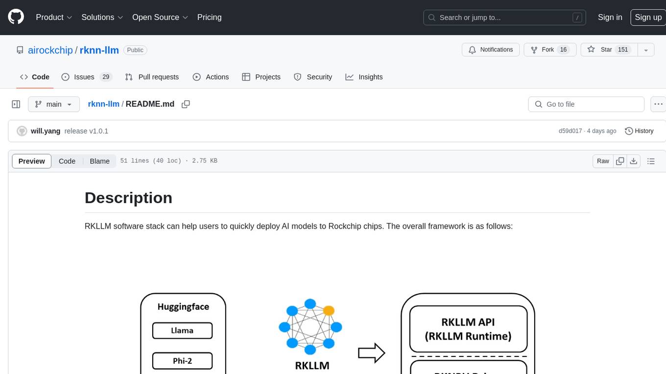
rknn-llm
RKLLM software stack is a toolkit designed to help users quickly deploy AI models to Rockchip chips. It consists of RKLLM-Toolkit for model conversion and quantization, RKLLM Runtime for deploying models on Rockchip NPU platform, and RKNPU kernel driver for hardware interaction. The toolkit supports RK3588 and RK3576 series chips and various models like TinyLLAMA, Qwen, Phi, ChatGLM3, Gemma, InternLM2, and MiniCPM. Users can download packages, docker images, examples, and docs from RKLLM_SDK. Additionally, RKNN-Toolkit2 SDK is available for deploying additional AI models.
awesome-RK3588
RK3588 is a flagship 8K SoC chip by Rockchip, integrating Cortex-A76 and Cortex-A55 cores with NEON coprocessor for 8K video codec. This repository curates resources for developing with RK3588, including official resources, RKNN models, projects, development boards, documentation, tools, and sample code.